Related Questions14 Items
Q1.M-MCQ
All the diodes in the circuit given below are ideal.
Which of the following plots is/are correct when $VI$ (in Volts) is swept from $-M$ to $M$
!image(https://uadmin.udsfgecw.tech/file/download/public/public:1b338c47-a9c8-4cca-b58b-762756cc3a8b.jpeg)
Q2.MCQ
!image(https://uadmin.udsfgecw.tech/file/download/public/public:4f41ee08-cca8-4c6d-b4c3-604d491b73b8.jpg)A simplified small-signal equivalent circuit of a BJT-based amplifier is given below.
The small-signal voltage gain $Vo/Vs$ (in $V/V$) is .
Q3.MCQ
!image(https://uadmin.udsfgecw.tech/file/download/public/public:5bdb3f71-fe5c-4b8c-b430-e2400f1454af.jpg)The ideal BJT in the circuit given below is biased in the active region with a $\beta$ of 100.
If $IB$ is $10 \mu A$, then $V{CE}$ (in Volts, rounded off to two decimal places) is .
Q4.M-MCQ
Which of the following plots is/are correct when $VI$ (in Volts) is swept from $-M$ to $M$?
!image(https://uadmin.udsfgecw.tech/file/download/public/public:bfc43f4e-2e9b-4f1f-99ea-a3cf939bff42.jpg)All the diodes in the circuit given below are ideal.
Q5.MCQ
!image(https://uadmin.udsfgecw.tech/file/download/public/public:11558c5a-fc3f-42a4-b861-2f6ce01014a1.png)The identical MOSFETs $M1$ and $M2$ in the circuit given below are ideal and biased in the saturation region. $M1$ and $M2$ have a transconductance $gm$ of $5$ mS.
The input signals (in Volts) are:
$V1 = 2.5 + 0.01 \sin \omega t$
$V2 = 2.5 - 0.01 \sin \omega t$
The output signal $V3$ (in Volts) is \\\\\\\\.
image needed to be inserted here
Q6.MCQ
!image(https://uadmin.udsfgecw.tech/file/download/public/public:c23ff8a6-e30e-45f6-9e47-2fe6ff270ffc.png)In the circuit shown, the identical transistors $Q1$ and $Q2$ are biased in the active region with $\beta = 120$. The Zener diode is in the breakdown region with $VZ = 5$ V and $IZ = 25$ mA.
If $IL = 12$ mA and $V{EB1} = V{EB2} = 0.7$ V, then the values of $R1$ and $R2$ (in k$\Omega$, rounded off to one decimal place) are \\\\\\\\, respectively.
image needed to be inserted here
Q7.M-MCQ
Which of the following statements is/are TRUE with respect to an ideal opamp?
Q8.M-MCQ
Which of the following statements is/are TRUE with respect to ideal MOSFET-based DC-coupled single-stage amplifiers having finite load resistors?
Q9.NUMERICAL
All the components in the bandpass filter given below are ideal. The lower $-3$ dB frequency of the filter is $1$ MHz.
The upper $-3$ dB frequency (in MHz, rounded off to the nearest integer) is \\\\\\\.
!image(https://uadmin.udsfgecw.tech/file/download/public/public:25a6a0af-6416-42ba-bb3f-f9a8b19d480e.jpg)
Q10.MCQ
In the circuit below, assume that the long channel NMOS transistor is biased in saturation. The small signal trans-conductance of the transistor is $gm$. Neglect body effect, channel length modulation and intrinsic device capacitances. The small signal input impedance $Z{in}(j\omega)$ is \\\\\\\.
!image(https://uadmin.udsfgecw.tech/file/download/public/public:8fc6a370-c697-4773-b2b0-90519220aee6.jpg)
Q11.MCQ
For the closed loop amplifier circuit shown below, the magnitude of open loop low frequency small signal voltage gain is $40$. All the transistors are biased in saturation. The current source $I{SS}$ is ideal. Neglect body effect, channel length modulation and intrinsic device capacitances. The closed loop low frequency small signal voltage gain $\frac{v{out}}{v{in}}$ (rounded off to three decimal places) is \\\\\\.
!image(https://uadmin.udsfgecw.tech/file/download/public/public:4d0e233d-3638-4773-b562-c1ddec543bda.jpg)
Q12.MCQ
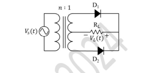
In the circuit shown, the $n:1$ step-down transformer and the diodes are ideal. The diodes have no voltage drop in forward biased condition. If the input voltage (in Volts) is $Vs(t) = 10 \sin \omega t$ and the average value of load voltage $VL(t)$ (in Volts) is $2.5/\pi$, the value of $n$ is .
!image(https://uadmin.udsfgecw.tech/file/download/public/public:00fb256e-8978-4637-ab48-7ba47118b218.jpg)
Q13.MCQ
The opamps in the circuit shown are ideal, but have saturation voltages of $\pm 10\text{ V}$.
!image(https://uadmin.udsfgecw.tech/file/download/public/public:eb592447-7642-49be-9dea-464014dfa871.jpg)
Assume that the initial inductor current is $0\text{ A}$. The input voltage ($Vi$) is a triangular signal with peak voltages of $\pm 2\text{ V}$ and time period of $8\text{ }\mu\text{s}$. Which one of the following statements is true?
Q14.MCQ
In the circuit below, the opamp is ideal.
!image(https://uadmin.udsfgecw.tech/file/download/public/public:5636e95a-6d69-4cbc-b52a-b860efb4a024.jpg)
If the circuit is to show sustained oscillations, the respective values of $R1$ and the corresponding frequency of oscillation are .
Electronics EngineeringAnalog CircuitsMultiple Choice (MCQ)1 Mark
Q12.
In the circuit shown, the n:1 step-down transformer and the diodes are ideal. The diodes have no voltage drop in forward biased condition. If the input voltage (in Volts) is Vs(t)=10sinωt and the average value of load voltage VL(t) (in Volts) is 2.5/π, the value of n is ____.
A
4
B
8
C
12
D
16