Related Questions14 Items
Q1.M-MCQ
All the diodes in the circuit given below are ideal.
Which of the following plots is/are correct when $VI$ (in Volts) is swept from $-M$ to $M$
!image(https://uadmin.udsfgecw.tech/file/download/public/public:1b338c47-a9c8-4cca-b58b-762756cc3a8b.jpeg)
Q2.MCQ
!image(https://uadmin.udsfgecw.tech/file/download/public/public:4f41ee08-cca8-4c6d-b4c3-604d491b73b8.jpg)A simplified small-signal equivalent circuit of a BJT-based amplifier is given below.
The small-signal voltage gain $Vo/Vs$ (in $V/V$) is .
Q3.MCQ
!image(https://uadmin.udsfgecw.tech/file/download/public/public:5bdb3f71-fe5c-4b8c-b430-e2400f1454af.jpg)The ideal BJT in the circuit given below is biased in the active region with a $\beta$ of 100.
If $IB$ is $10 \mu A$, then $V{CE}$ (in Volts, rounded off to two decimal places) is .
Q4.M-MCQ
Which of the following plots is/are correct when $VI$ (in Volts) is swept from $-M$ to $M$?
!image(https://uadmin.udsfgecw.tech/file/download/public/public:bfc43f4e-2e9b-4f1f-99ea-a3cf939bff42.jpg)All the diodes in the circuit given below are ideal.
Q5.MCQ
!image(https://uadmin.udsfgecw.tech/file/download/public/public:11558c5a-fc3f-42a4-b861-2f6ce01014a1.png)The identical MOSFETs $M1$ and $M2$ in the circuit given below are ideal and biased in the saturation region. $M1$ and $M2$ have a transconductance $gm$ of $5$ mS.
The input signals (in Volts) are:
$V1 = 2.5 + 0.01 \sin \omega t$
$V2 = 2.5 - 0.01 \sin \omega t$
The output signal $V3$ (in Volts) is \\\\\\\\.
image needed to be inserted here
Q6.MCQ
!image(https://uadmin.udsfgecw.tech/file/download/public/public:c23ff8a6-e30e-45f6-9e47-2fe6ff270ffc.png)In the circuit shown, the identical transistors $Q1$ and $Q2$ are biased in the active region with $\beta = 120$. The Zener diode is in the breakdown region with $VZ = 5$ V and $IZ = 25$ mA.
If $IL = 12$ mA and $V{EB1} = V{EB2} = 0.7$ V, then the values of $R1$ and $R2$ (in k$\Omega$, rounded off to one decimal place) are \\\\\\\\, respectively.
image needed to be inserted here
Q7.M-MCQ
Which of the following statements is/are TRUE with respect to an ideal opamp?
Q8.M-MCQ
Which of the following statements is/are TRUE with respect to ideal MOSFET-based DC-coupled single-stage amplifiers having finite load resistors?
Q9.NUMERICAL
All the components in the bandpass filter given below are ideal. The lower $-3$ dB frequency of the filter is $1$ MHz.
The upper $-3$ dB frequency (in MHz, rounded off to the nearest integer) is \\\\\\\.
!image(https://uadmin.udsfgecw.tech/file/download/public/public:25a6a0af-6416-42ba-bb3f-f9a8b19d480e.jpg)
Q10.MCQ
In the circuit below, assume that the long channel NMOS transistor is biased in saturation. The small signal trans-conductance of the transistor is $gm$. Neglect body effect, channel length modulation and intrinsic device capacitances. The small signal input impedance $Z{in}(j\omega)$ is \\\\\\\.
!image(https://uadmin.udsfgecw.tech/file/download/public/public:8fc6a370-c697-4773-b2b0-90519220aee6.jpg)
Q11.MCQ
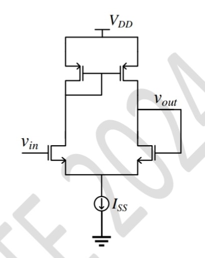
For the closed loop amplifier circuit shown below, the magnitude of open loop low frequency small signal voltage gain is $40$. All the transistors are biased in saturation. The current source $I{SS}$ is ideal. Neglect body effect, channel length modulation and intrinsic device capacitances. The closed loop low frequency small signal voltage gain $\frac{v{out}}{v{in}}$ (rounded off to three decimal places) is \\\\\\.
!image(https://uadmin.udsfgecw.tech/file/download/public/public:4d0e233d-3638-4773-b562-c1ddec543bda.jpg)
Q12.MCQ
In the circuit shown, the $n:1$ step-down transformer and the diodes are ideal. The diodes have no voltage drop in forward biased condition. If the input voltage (in Volts) is $Vs(t) = 10 \sin \omega t$ and the average value of load voltage $VL(t)$ (in Volts) is $2.5/\pi$, the value of $n$ is .
!image(https://uadmin.udsfgecw.tech/file/download/public/public:00fb256e-8978-4637-ab48-7ba47118b218.jpg)
Q13.MCQ
The opamps in the circuit shown are ideal, but have saturation voltages of $\pm 10\text{ V}$.
!image(https://uadmin.udsfgecw.tech/file/download/public/public:eb592447-7642-49be-9dea-464014dfa871.jpg)
Assume that the initial inductor current is $0\text{ A}$. The input voltage ($Vi$) is a triangular signal with peak voltages of $\pm 2\text{ V}$ and time period of $8\text{ }\mu\text{s}$. Which one of the following statements is true?
Q14.MCQ
In the circuit below, the opamp is ideal.
!image(https://uadmin.udsfgecw.tech/file/download/public/public:5636e95a-6d69-4cbc-b52a-b860efb4a024.jpg)
If the circuit is to show sustained oscillations, the respective values of $R1$ and the corresponding frequency of oscillation are .
Electronics EngineeringAnalog CircuitsMultiple Choice (MCQ)1 Mark
Q11.
For the closed loop amplifier circuit shown below, the magnitude of open loop low frequency small signal voltage gain is 40. All the transistors are biased in saturation. The current source ISS is ideal. Neglect body effect, channel length modulation and intrinsic device capacitances. The closed loop low frequency small signal voltage gain vinvout (rounded off to three decimal places) is ______.
A
0.976
B
1.000
C
1.025
D
0.488