Related Questions9 Items
Q1.MCQ
!image(https://uadmin.udsfgecw.tech/file/download/public/public:efe5c249-815a-4165-a954-fda94a080c40.png)In the circuit below, $M1$ is an ideal AC voltmeter and $M2$ is an ideal AC ammeter. The source voltage (in Volts) is $vs(t) = 100 \cos(200t)$.
What should be the value of the variable capacitor $C$ such that the RMS readings on $M1$ and $M2$ are $25\text{ V}$ and $5\text{ A}$, respectively?
Q2.MCQ
The $Z$-parameter matrix of a two port network relates the port voltages and port currents as follows:
$$\begin{bmatrix} V1 \\ V2 \end{bmatrix} = Z \begin{bmatrix} I1 \\ I2 \end{bmatrix}$$
The $Z$-parameter matrix (with each entry in Ohms) of the network shown below is .
!image(https://uadmin.udsfgecw.tech/file/download/public/public:883a1cd8-ece4-4e39-aa0d-b2f96d6ee25d.png)
Q3.MCQ
!image(https://uadmin.udsfgecw.tech/file/download/public/public:f7f4252c-3d6c-486e-a69b-417c0293a086.jpg)Consider a part of an electrical network as shown below. Some node voltages, and the current flowing through the $3\ \Omega$ resistor are as indicated.
The voltage (in Volts) at node $X$ is .
Q4.MCQ
!image(https://uadmin.udsfgecw.tech/file/download/public/public:f59191f5-ec6a-44fd-b75a-65924050e4f2.jpg)Let $iC$, $iL$, and $iR$ be the currents flowing through the capacitor, inductor, and resistor, respectively, in the circuit given below. The AC admittances are given in Siemens ($S$). Which one of the following is TRUE?
Q5.NUMERICAL
!image(https://uadmin.udsfgecw.tech/file/download/public/public:49d71e82-54b7-493a-960e-c6d53ff4f5f4.png)In the given circuit, the current $Ix$ (in mA) is .
Q6.NUMERICAL
!image(https://uadmin.udsfgecw.tech/file/download/public/public:a42357c7-e909-483d-9f20-48a8d7dbe793.png)In the circuit given below, the switch $S$ was kept open for a sufficiently long time and is closed at time $t = 0$. The time constant (in seconds) of the circuit for $t > 0$ is .
Q7.NUMERICAL
As shown in the circuit, the initial voltage across the capacitor is $10 \text{ V}$, with the switch being open. The switch is then closed at $t = 0$. The total energy dissipated in the ideal Zener diode ($VZ = 5 \text{ V}$) after the switch is closed (in mJ, rounded off to three decimal places) is .
!image(https://uadmin.udsfgecw.tech/file/download/public/public:3b3192bd-fb8e-464b-bfc2-46c351a182a3.png)
Q8.NUMERICAL
For the two port network shown below, the value of the $Y{21}$ parameter (in Siemens) is .!image(https://uadmin.udsfgecw.tech/file/download/public/public:5491340c-5218-4295-b4e1-233c39b25485.jpg)
Q9.NUMERICAL
In the network shown below, maximum power is to be transferred to the load $RL$.
!image(https://uadmin.udsfgecw.tech/file/download/public/public:314e8ec3-e43b-4526-93f8-ab79c80c819d.jpg)
The value of $RL$ (in $\Omega$) is .
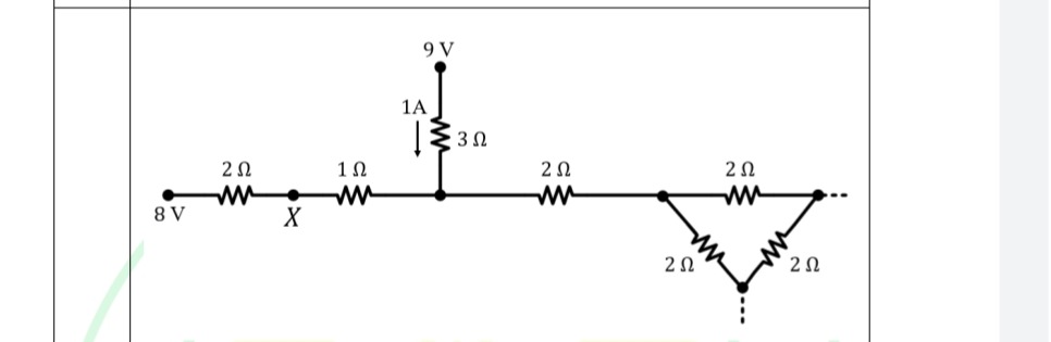 Consider a part of an electrical network as shown below. Some node voltages, and the current flowing through the