Related Questions9 Items
Q1.MCQ
!image(https://uadmin.udsfgecw.tech/file/download/public/public:efe5c249-815a-4165-a954-fda94a080c40.png)In the circuit below, $M1$ is an ideal AC voltmeter and $M2$ is an ideal AC ammeter. The source voltage (in Volts) is $vs(t) = 100 \cos(200t)$.
What should be the value of the variable capacitor $C$ such that the RMS readings on $M1$ and $M2$ are $25\text{ V}$ and $5\text{ A}$, respectively?
Q2.MCQ
The $Z$-parameter matrix of a two port network relates the port voltages and port currents as follows:
$$\begin{bmatrix} V1 \\ V2 \end{bmatrix} = Z \begin{bmatrix} I1 \\ I2 \end{bmatrix}$$
The $Z$-parameter matrix (with each entry in Ohms) of the network shown below is .
!image(https://uadmin.udsfgecw.tech/file/download/public/public:883a1cd8-ece4-4e39-aa0d-b2f96d6ee25d.png)
Q3.MCQ
!image(https://uadmin.udsfgecw.tech/file/download/public/public:f7f4252c-3d6c-486e-a69b-417c0293a086.jpg)Consider a part of an electrical network as shown below. Some node voltages, and the current flowing through the $3\ \Omega$ resistor are as indicated.
The voltage (in Volts) at node $X$ is .
Q4.MCQ
!image(https://uadmin.udsfgecw.tech/file/download/public/public:f59191f5-ec6a-44fd-b75a-65924050e4f2.jpg)Let $iC$, $iL$, and $iR$ be the currents flowing through the capacitor, inductor, and resistor, respectively, in the circuit given below. The AC admittances are given in Siemens ($S$). Which one of the following is TRUE?
Q5.NUMERICAL
!image(https://uadmin.udsfgecw.tech/file/download/public/public:49d71e82-54b7-493a-960e-c6d53ff4f5f4.png)In the given circuit, the current $Ix$ (in mA) is .
Q6.NUMERICAL
!image(https://uadmin.udsfgecw.tech/file/download/public/public:a42357c7-e909-483d-9f20-48a8d7dbe793.png)In the circuit given below, the switch $S$ was kept open for a sufficiently long time and is closed at time $t = 0$. The time constant (in seconds) of the circuit for $t > 0$ is .
Q7.NUMERICAL
As shown in the circuit, the initial voltage across the capacitor is $10 \text{ V}$, with the switch being open. The switch is then closed at $t = 0$. The total energy dissipated in the ideal Zener diode ($VZ = 5 \text{ V}$) after the switch is closed (in mJ, rounded off to three decimal places) is .
!image(https://uadmin.udsfgecw.tech/file/download/public/public:3b3192bd-fb8e-464b-bfc2-46c351a182a3.png)
Q8.NUMERICAL
For the two port network shown below, the value of the $Y{21}$ parameter (in Siemens) is .!image(https://uadmin.udsfgecw.tech/file/download/public/public:5491340c-5218-4295-b4e1-233c39b25485.jpg)
Q9.NUMERICAL
In the network shown below, maximum power is to be transferred to the load $RL$.
!image(https://uadmin.udsfgecw.tech/file/download/public/public:314e8ec3-e43b-4526-93f8-ab79c80c819d.jpg)
The value of $RL$ (in $\Omega$) is .
Electronics EngineeringNetwork TheoryMultiple Choice (MCQ)2 Marks
Q1.
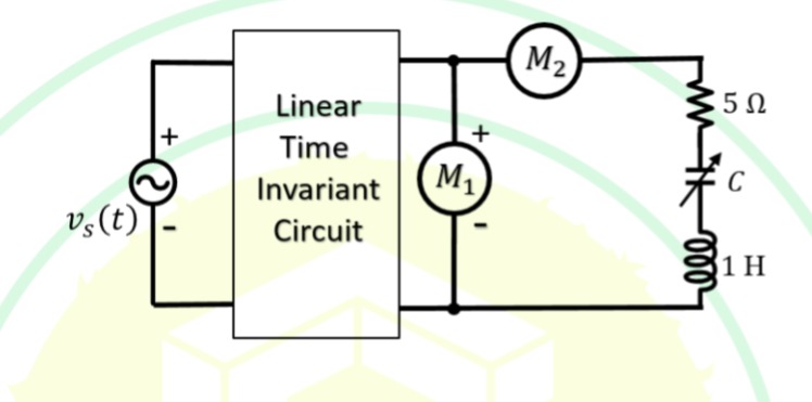 In the circuit below, M1 is an ideal AC voltmeter and M2 is an ideal AC ammeter. The source voltage (in Volts) is vs(t)=100cos(200t).
What should be the value of the variable capacitor C such that the RMS readings on M1 and M2 are 25 V and 5 A, respectively?
A
25 μF
B
4 μF
C
0.25 μF
D
Insufficient information to find C